Most control panel problems on site were decided weeks earlier, at the desk. A missing load, an undersized breaker or an unchecked heat figure can all turn into rework once the panel is wired and delivered.
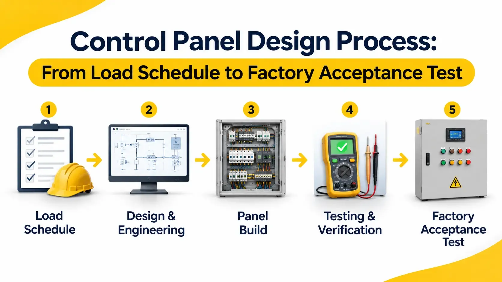
A clear control panel design process prevents that. It moves from the load schedule through sizing, drawings and build to a factory acceptance test (FAT), and each stage catches a different kind of error before it reaches your plant in the UAE.
This guide walks through all eight stages, what to produce at each one, and what to check before you sign off.
Why the Control Panel Design Process Matters
Fixing a mistake on a drawing takes minutes. Fixing the same mistake in a wired panel takes days, and fixing it on site during a shutdown costs far more.
A structured process also gives every party something to approve. The client signs off the load schedule, then the drawings, then the FAT report. Nobody is guessing what was agreed.
It also protects maintenance. A panel built from approved drawings and handed over with complete documentation is far easier to fault-find and expand years later.
Control Panel Design Process: Eight Stages at a Glance
- Requirements and load schedule
- Sizing and component selection
- Thermal design and enclosure selection
- Drawings and documentation
- Design review and approval
- Build and wiring
- Pre-FAT checks and factory acceptance test
- Delivery, site testing and handover
The sections below cover each stage in the order a project follows.
Stage 1: Requirements and Load Schedule
Every good panel starts with a load schedule. It is the list of every electrical load the panel will feed or control, with the data needed to size everything else.
What a load schedule should include
- Load tag and description (for example, P-101 transfer pump)
- Rated power in kW and full-load current in amps
- Supply voltage, phase and frequency
- Starting method: direct-on-line, star-delta, soft starter or VFD
- Duty type: continuous, intermittent or standby
- Control method: PLC, hardwired or local only
- Protection needed: overload, short circuit, earth fault
- Future spare capacity
A simple example shows why this matters. Take a pump station with two 15 kW duty pumps, one 15 kW standby pump and a 5.5 kW fan. Connected load is 50.5 kW, but the normal running load is only 35.5 kW because the standby pump does not run with the others. A 15 kW motor at 400 V draws roughly 28 A, so the incoming supply and busbars need sizing from the real running pattern, not a guess.
Site and standards inputs
Capture these at the same time:
- Ambient temperature range and whether the panel sits in shade or direct sun
- Indoor or outdoor location, dust and moisture exposure
- Available fault level at the incoming supply
- Required standard, such as IEC or UL, and any client or consultant specification
- Preferred component brands and any existing site standards
Leaving the standard to the end is a common mistake. It affects component choice, spacing and documentation, so confirm it at the start.
Stage 2: Sizing and Component Selection
With the load schedule approved, size the protection and power components in a logical order.
- Incoming device and busbars: Size for the running load plus spare capacity, and check the breaker's short-circuit rating against the fault level at site.
- Motor protection: Coordinate breakers, contactors and overload relays so a fault trips the right device.
- VFDs and soft starters: Size to motor current and load type, not just kW.
- PLC and I/O: Count every input and output, then add spare channels. Fifteen to twenty percent spare is a common allowance.
- 24 VDC power supply: Add up the control load and keep margin for growth.
- Cables and terminals: Size for current, voltage drop and routing distance.
Component availability deserves attention at this stage. A specified part with a six-week lead time can hold up an otherwise ready project, so check stock early. Our guide on automation spare parts lead time explains how UAE plants avoid that wait.
Stage 3: Thermal Design and Enclosure Selection
Heat is where many panels fail in the UAE. Drives, power supplies and contactors all give off heat inside a closed enclosure, and outdoor ambient temperatures can already be very high.
Start with a heat budget. Add up the heat loss of every major component, since a VFD typically dissipates a few percent of its rated power as heat. Then compare the total with what the enclosure can shed.
If natural cooling is not enough, choose between filtered fans, heat exchangers or an enclosure air conditioner. Enclosure rating matters too. IP54 suits many indoor areas, while IP65 is common where dust or washdown is expected.
For sizing methods, see our article on control panel cooling in UAE heat.
Stage 4: Drawings and Documentation
Drawings turn the design into something that can be built, checked and maintained. A complete set usually includes:
- Single-line diagram showing power distribution and protection
- Power and control schematics with wire numbers
- General arrangement drawing with enclosure dimensions and component layout
- Terminal plan and cable schedule
- I/O list linking each PLC channel to its field device
- Bill of materials with part numbers and quantities
- Label and nameplate schedule
Good drawings must match what gets built. Doing drafting in-house keeps design and workshop aligned and speeds up revisions. That is how our custom control panel design and manufacturing team works, with drawings issued for sign-off before any wiring starts.
Stage 5: Design Review and Approval
Before the build begins, review the design with everyone who will rely on it. This is the last cheap point to make changes.
Check these items:
- The load schedule still matches the process and equipment list
- Breaker ratings and short-circuit rating suit the site fault level
- The heat budget and cooling method are documented
- Every I/O point has a tag, a terminal and a drawing reference
- Labels, language and colour coding match site practice
- Emergency stop, interlock and safety circuits are clear
Once the drawings are approved, treat them as frozen. Any later change goes through a written change request, so the build and the documents never drift apart.
Stage 6: Build and Wiring
Build quality shows in the details. Components are mounted to the approved layout, power and control wiring are separated, and every wire is ferruled, numbered and torqued.
Pay particular attention to:
- Segregation: Keep power cables away from low-level signal wiring to limit interference.
- Shielding and earthing: Servo and VFD cables need proper screen termination and a clean earth path.
- Clearances: Leave space for heat movement and for maintenance access.
- Labelling: Mark devices, wires and terminals to match the drawings exactly.
Many UAE projects also require a recognised assembly standard. Our article on IEC 61439 compliance lists what contractors should verify in a finished panel.
Stage 7: Pre-FAT Checks and the Factory Acceptance Test
The factory acceptance test is a formal check, at the manufacturer's workshop, that the finished panel matches the approved design and works as intended. It happens before the panel ships, when fixes are still quick and cheap.
Pre-FAT checks
The workshop completes internal checks first, so the FAT itself runs smoothly:
- Visual and dimensional check against the general arrangement drawing
- Component and label check against the bill of materials
- Point-to-point wiring continuity check
- Terminal tightness and wiring workmanship check
A practical FAT checklist
- Confirm the panel matches the approved drawings and bill of materials.
- Run insulation resistance and dielectric tests as the applicable standard requires.
- Power up in stages and verify supply voltages at every level.
- Simulate field inputs and confirm each PLC input and output against the I/O list.
- Test interlocks, emergency stops and safety circuits.
- Run VFDs, soft starters and motor starters under test conditions.
- Trigger alarms and trips to confirm they operate and display correctly.
- Record results, list any punch items and re-test after each fix.
Where the panel includes PLC logic, loading and testing the program at this stage proves the hardware and software together. See our PLC programming services for how logic and HMI are tested alongside the panel.
Clients should be invited to witness the FAT. A signed FAT report becomes the agreed proof that the panel is ready to ship.
Stage 8: Delivery, Site Testing and Handover
After FAT, the panel is protected for transport, delivered and installed. Site acceptance testing (SAT) then confirms it works correctly with the real field devices and cabling.
The handover package should include:
- As-built drawings that reflect any changes made during build
- Loop diagrams and the final I/O list
- Bill of materials and recommended spare parts
- The signed FAT report
- Datasheets and manuals for key components
For loop checks, energisation and start-up on site, see our commissioning and start-up services.
How Long Does the Control Panel Design Process Take?
For a standard custom panel, the process typically follows these timings:
- Enquiry and requirements review: 1 to 2 working days
- Drafting and approval: 3 to 5 working days
- Manufacturing and wiring: 5 to 7 working days
- Factory acceptance test: about 1 working day
- Total: typically 10 to 15 working days
Simple single-drive panels can be faster. Large MCC line-ups often take three to four weeks, mainly because of component lead times. Exact timelines are confirmed after the specification is reviewed.
Common Mistakes That Cause Site Rework
- Starting design before the load schedule is approved
- Ignoring the site fault level when selecting breakers
- Skipping the heat budget in hot climates
- Leaving no spare I/O or breaker space for expansion
- Changing drawings during build without updating documents
- Treating FAT as a quick power-on check instead of a full test
- Receiving a panel without as-built drawings or loop diagrams
Keeping Panels Reliable After Handover
A well-built panel still needs care. Dust, heat and loose terminations build up over time, and a planned inspection routine catches them early. Our AMC services for panels, VFDs, UPS and servo drives cover scheduled inspections and support after installation.
Frequently Asked Questions
What is a load schedule in control panel design?
A load schedule is a list of every load a panel feeds or controls, with its power, current, voltage, starting method and duty. It is the basis for sizing breakers, cables, drives and busbars, so it is the first document approved in the design process.
What is a factory acceptance test (FAT) for a control panel?
A FAT is a formal test carried out at the manufacturer's workshop before shipping. It checks the panel against the approved drawings, then tests wiring, insulation, interlocks, PLC I/O and drives. A signed FAT report records that the panel is ready for delivery.
What is the difference between FAT and SAT?
FAT happens at the factory, with simulated inputs, before the panel ships. SAT happens on site after installation, with the real field devices, cables and process connected. FAT catches build and design faults early, and SAT confirms the whole system works in place.
How long does the control panel design process take?
A standard custom panel typically takes 10 to 15 working days from enquiry to delivery. Large MCC panels can take three to four weeks, depending on component lead times and complexity.
What documents should I receive with a finished control panel?
You should receive as-built drawings, loop diagrams, the I/O list, a bill of materials, the signed FAT report and component datasheets. These let your team maintain and expand the panel without reverse-engineering the wiring.
Plan Your Next Control Panel With a Clear Process
A clear process saves time at every stage, from the first load schedule to the signed FAT report. If you have a panel project coming up, bring your equipment list and site details and we will review them with you.
General Tech Automation designs, builds and tests custom panels from its Sharjah workshop for projects across the UAE. Call +971 6 543 6933 or contact our team for a fixed quote and delivery timeline.