A plant can pass every mechanical and electrical inspection and still fail on day one of start-up. The reason is usually small: a transmitter wired to the wrong I/O channel, a valve that strokes in reverse, or an alarm that never reaches the operator screen.
A structured loop check procedure catches these faults while the plant is still cold and the cost of fixing them is low. This guide explains how an instrument loop check works, what to prepare, and the exact steps to follow before commissioning. It is written for UAE contractors, plant engineers and commissioning teams.
What Is a Loop Check in Instrumentation?
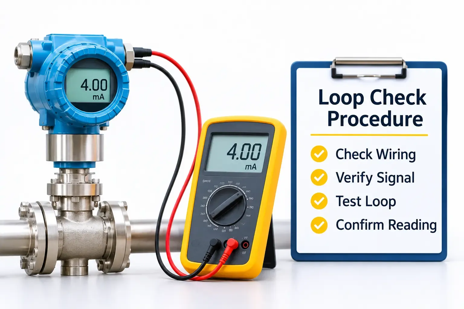
A loop check in instrumentation is a test that proves a complete signal path works end to end. It follows the signal from the field instrument, through the junction box, marshalling cabinet and I/O card, into the DCS or PLC, and back out to the final element, such as a control valve.
In simple terms, an instrument loop check answers three questions:
- Does the right device respond when the signal changes?
- Does the control system read or drive it correctly, in the right units and range?
- Do the alarms, trips and interlocks tied to that loop act as designed?
Each loop is tested on its own and signed off against its tag number. That tag-by-tag record becomes part of the handover package.
Why Loop Check Before Commissioning Is Non-Negotiable
Loop testing is the last chance to find wiring and configuration errors before process fluid, steam or product is involved. Finding a swapped pair in a marshalling cabinet takes minutes with the plant shut down. Finding it during a live start-up can mean a trip, a spill or a lost shift.
For UAE projects, the pressure is higher for three reasons:
- Compressed schedules. Multiple contractors often finish work close to the go-live date, so the loop check window is short.
- Regulated and high-risk sites. Oil and gas, power and pharmaceutical plants need documented proof that each loop works. Our guide on automation priorities for ADNOC suppliers and contractors shows how much weight reliability documentation carries in these sectors.
- Harsh conditions. Heat, dust and humidity expose weak terminations and poorly sealed field junction boxes early.
A thorough loop check before commissioning also protects the project team. A signed loop record shows exactly what was tested, by whom, and when.
Loop Check vs Calibration vs FAT and SAT
These terms are often mixed up, so it helps to separate them.
- Calibration: proves the instrument measures accurately against a reference. It is done on the bench or in situ, before or during loop testing.
- Loop check: proves the whole signal path works and is configured correctly. It happens after installation and before start-up.
- FAT (Factory Acceptance Test): proves the panel or system works as built, at the supplier's facility. It happens before shipment. See our control panel design process from load schedule to FAT.
- SAT (Site Acceptance Test): proves the installed system works on site as specified. It happens after installation and loop checks.
Calibration confirms the instrument. The loop check confirms everything around it. You need both, and the loop test is only meaningful once the instrument itself is known to be accurate.
What to Prepare Before You Start
Good preparation cuts the loop testing procedure time sharply. Gather the following before anyone goes to the field.
Documents
- Loop folder or loop diagrams for every tag
- Instrument index and I/O list
- P&IDs and cause-and-effect matrices
- Instrument datasheets with ranges, units and alarm setpoints
- Approved loop check sheet template
Tools and equipment
- Loop calibrator or mA simulator and a multimeter
- HART communicator or handheld configurator
- Hand pump or pressure source, where pressure instruments are involved
- Radios, since two-person communication between field and control room is essential
- Certified intrinsically safe test equipment for hazardous areas
People and permits
- One technician at the field device and one at the DCS, PLC or HMI
- Work permits, isolation and lock-out arrangements
- A named person to approve and sign each completed loop
Loop Check Procedure: Step-by-Step
Use this step-by-step loop check as the backbone of your site procedure. Adapt tolerances and acceptance criteria to the project specification.
Step 1: Verify Documents and Tag Data
Confirm that the loop diagram, I/O list and datasheet agree with each other. Check tag number, range, engineering units, signal type and alarm limits.
Resolve mismatches now. A range that differs between the datasheet and the DCS configuration is one of the most common causes of wrong readings.
Step 2: Inspect the Installation
Walk the loop physically before applying any signal. Check that:
- The instrument is mounted correctly and the tag plate matches the drawings
- Impulse lines, process connections and cable glands are fitted and tight
- Cable tags and terminal labels match the loop diagram
- Earthing and shielding are connected as designed
- Hazardous-area equipment and barriers carry the correct certification and labels
This is also the point to confirm that the field work matches the design intent. Teams that rely on field instrumentation installation and support from the same provider usually find fewer surprises here, because the installer and tester share the same standards.
Step 3: Check Wiring, Power and Insulation
With the loop de-energised, test continuity from the field device to the marshalling cabinet and on to the I/O terminal. Check polarity, shield continuity and insulation resistance where the specification requires it.
Then confirm the loop power supply voltage at the terminals. A transmitter that is under-powered will often read normally at 12 mA and fail at 20 mA.
Step 4: Test Input Loops (Transmitters and Sensors)
For 4–20 mA transmitters, simulate the measured variable or inject a signal and compare the field reading with the control system reading.
Use a five-point check as a standard approach:
- 4 mA (0% of span): the control system should show the bottom of the range
- 8 mA (25% of span): one quarter of the range
- 12 mA (50% of span): mid-range
- 16 mA (75% of span): three quarters of the range
- 20 mA (100% of span): the top of the range
Record the reading at each point and compare it with the tolerance in the project specification. Also check what happens beyond the range. The system should flag under-range, over-range and broken-wire conditions, not display a plausible but false value.
For temperature elements such as RTDs and thermocouples, simulate resistance or millivolts at the head and confirm the displayed temperature and units.
Step 5: Test Output Loops (Control Valves and Final Elements)
Output loops work in reverse. The control system sends a command and the field device must respond.
From the DCS or PLC, drive the output to 0%, 25%, 50%, 75% and 100%, and check:
- The valve or actuator moves to the matching position
- The position feedback on the screen agrees with the physical position
- Direction of action is correct (air-to-open or air-to-close)
- Stroke time is within specification
- The valve moves to its fail-safe position when signal or air is removed
Never stroke a valve without confirming that the process side is isolated or that the move is safe.
Step 6: Test Discrete Loops and Interlocks
For switches, push buttons, motor status signals and trip inputs, operate the field contact and confirm the state change on the screen. Then test the logic that depends on it.
Walk through the cause-and-effect matrix. For each cause, trigger the input and verify that every listed effect occurs. Loops that belong to a safety instrumented function need extra care and should follow the project's functional safety procedure, typically aligned with IEC 61511.
Step 7: Verify Alarms, Trips and Setpoints
Simulate values that cross each alarm and trip limit, and confirm that the alarm:
- Appears with the correct tag, description and priority
- Triggers at the configured value
- Clears and resets properly
- Reaches the operator screen, historian and alarm log
This is where the control logic and operator interface come together. If you need the underlying logic reviewed or corrected, our PLC programming services cover logic, HMI and migration work across the main platforms.
Step 8: Confirm Communications and Diagnostics
For smart devices, confirm that HART, fieldbus or other digital communication works. Check device identification, configured range and diagnostic status, and make sure no active device alarms are left unresolved.
Also confirm that the value reaches higher layers correctly. Data that is right at the PLC but wrong in SCADA is still a failed loop. Plants running larger systems often review this alongside their PLC, DCS and SCADA automation architecture.
Step 9: Record Results and Close Out
Complete the loop check sheet for each tag with the readings, date, tester name and witness signature. Log any defect on a punch list with an owner and a retest date.
Do not mark a loop as passed until every defect is fixed and retested. Keep these records organised, because they feed directly into asset data and tag history for later maintenance and audits.
Worked Example: Level Transmitter and Control Valve Loop
Consider a tank level loop with a 4–20 mA level transmitter ranged 0–5 m, and a control valve on the outlet.
Input side
- Simulate 4, 8, 12, 16 and 20 mA at the transmitter terminals.
- The DCS should read 0, 1.25, 2.5, 3.75 and 5.0 m.
- Drop the signal below 3.6 mA and confirm a low-signal or wire-break alarm.
Output side
- Set the controller to manual and drive the valve to 0, 50 and 100%.
- Check the valve position against the screen at each point.
- Cut the air supply and confirm the valve moves to its fail position.
Alarms
- Simulate a high-high level and confirm the alarm and the pump trip occur as per the cause-and-effect matrix.
If every step matches the datasheet and loop diagram, the loop is signed off. If one reading is off, the error lies somewhere along the path, and the five-point log shows where to look first.
Common Loop Check Faults and How to Catch Them
Most failures during loop testing fall into a few patterns:
- Swapped or wrong channel. The right signal reaches the wrong tag. A tag-by-tag test catches it immediately.
- Range mismatch. The transmitter and the DCS use different ranges or units.
- Reversed action. A valve opens when it should close, or a controller acts in the wrong direction.
- Loose or poor terminations. Readings drift or jump, especially in hot, vibrating areas.
- Missing earth or shield connection. Noise appears on the signal and causes unstable readings.
- Wrong alarm configuration. Limits, priorities or descriptions differ from the design.
- Inadequate loop power. The loop works at low current but falls over at high current.
Writing these into your checklist turns past mistakes into a routine check.
Loop Check Checklist Before Start-Up
Use this short checklist before signing off a loop:
- Documents agree: loop diagram, I/O list, datasheet and DCS configuration
- Installation, tag plates and terminals checked
- Continuity, polarity and loop power verified
- Five-point signal test completed and recorded
- Control valve stroke, direction and fail action confirmed
- Discrete inputs and interlocks tested against cause and effect
- Alarms and trips verified on the operator screen
- Digital communication and diagnostics confirmed
- Results signed and witnessed; punch list items closed and retested
Loop Testing in UAE Plants: Practical Tips
Local conditions shape how a loop test should be run.
- Plan around heat. Schedule outdoor field testing for cooler hours to protect people and avoid readings affected by solar heating on instruments.
- Protect connections. Dust and humidity can compromise cable glands and junction boxes. Reseal anything you open during testing.
- Respect hazardous areas. Use certified test equipment and follow the permit system without exception.
- Coordinate contractors. Loop checks need electrical, mechanical and controls teams working in sequence. Agree the handover order early.
- Test early, not late. Where installation is progressing in sections, loop verification can start on completed areas instead of waiting for the entire plant.
When to Use a Commissioning Specialist
In-house teams can run loop checks on small projects. On larger or time-critical jobs, an independent specialist adds speed and a second set of eyes.
General Tech Automation's commissioning and start-up services cover installation verification, loop checking, calibration and operator training. Loop checking is typically completed within 24 hours per measurement point once site access is confirmed. The job closes with loop check records, calibration certificates and a signed acceptance report.
After start-up, scheduled measurement checks keep instruments accurate and give you an early warning when a loop begins to drift.
Frequently Asked Questions
What is the purpose of a loop check procedure?
A loop check procedure proves that every instrument loop works from the field device to the control system and back to the final element. It catches wiring errors, range mismatches, wrong valve action and alarm faults before start-up, when they are cheapest to fix.
How is an instrument loop check performed?
Two people work together, one at the field device and one at the DCS or PLC. They inject or simulate a signal at set points such as 0, 25, 50, 75 and 100%, compare readings on both ends, test valves and interlocks, verify alarms, and record the results on a signed loop check sheet.
What is the difference between a loop check and calibration?
Calibration checks that a single instrument measures accurately against a known reference. A loop check tests the entire signal path, including wiring, I/O, configuration, display and alarms. Both are needed before commissioning.
How long does a loop check take?
It depends on loop type and access. Simple transmitter loops can be tested quickly, while control valve and interlock loops take longer. Good preparation and early access to completed areas reduce the total time.
Who should perform a loop check?
Qualified instrumentation and control technicians, supported by an engineer who can approve results and resolve configuration questions. A client or third-party witness often signs off critical loops.
Final Thoughts
A disciplined loop check procedure turns commissioning from a risky switch-on into a controlled, documented handover. Verify the documents, test each loop step by step, record every result, and close every punch list item before start-up.
If you are planning a start-up in the UAE and want experienced hands on your loop testing, call General Tech Automation on +971 6 543 6933 or email mathews@generaltechuae.com to schedule your commissioning support.